Services / Design and Simulation
Design and simulation for automation equipment and robotic tooling.
SVS materials show mechanical design, layouts and robotic-cell concepts for manufacturing applications. Potential outputs include 2D drawings, 3D models and equipment layouts, agreed against the application and delivery scope.
Examples in the supplied profile include destacker tables, roller tables and robot grippers. Confirm the drawing package, formats and review stages for each engagement.
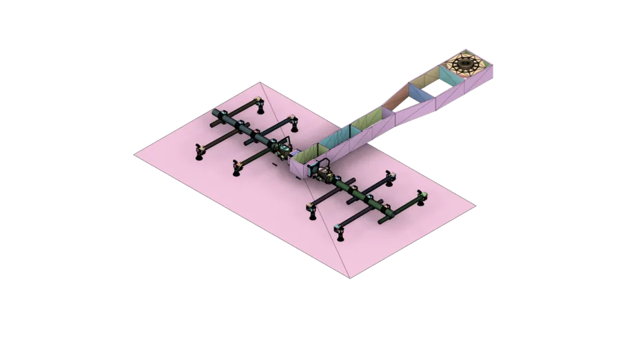
CAD concept from supplied profile. It is not identified as a drawing for any finished item shown elsewhere.
01 / Cell design and simulation
Describe the intended process and robot arrangement.
A cell concept can bring the process, robot placement, equipment interfaces and access needs into one layout. The supplied profile includes a candidate example, but reach, collision and cycle-time study scope must be confirmed before those analyses are promised.
Approved simulation export pending
A labelled, legible export should identify the application, robot arrangement and what was actually analysed.
02 / Tooling frame and arm design
Design around the part and mounting interface.
Supplied gripper material shows mounting frames, arms and round tooling elements. Geometry, robot connection, part mass and the handling motion shape the design requirement; the final assembly and manufacture scope need separate agreement.
Inputs for a tooling concept
Part model · robot and flange · pickup points · motion and access · target payload · tooling interface
03 / Centre of gravity and moment of inertia
Quantify the proposed tooling assembly.
The gripper document includes centre-of-gravity and moment-of-inertia work as a specific design example. Any published result must identify the part or assembly analysed, the assumptions used and the approved output. These calculations are not implied for every design enquiry.
Readable output pending
Request the full-resolution analysis export and confirm which assembly and revision it represents.
04 / Customised robot arrangements
Place and orient the robot for the task.
Supplied tooling material includes a customised robot-arrangement example. A specific design should explain its intended reach, rotation, work envelope and equipment interfaces after the original application is confirmed. No universal performance claim follows from one arrangement.
Arrangement review
Robot model · process path · reach envelope · access and guarding · part presentation · mounting constraints
05 / Machining simulation and offline programming
Keep each simulation deliverable clear.
The gripper material includes a machining or CAM example. That work differs from robotic-cell simulation and from PLC programming. Confirm the machine, toolpath, output and verification scope before describing an offline-programming deliverable.
Approved export pending
A readable machining example and its associated part identity are needed before an image is displayed.
06 / Design to manufacture
Carry the agreed design into equipment or tooling.
Drawings and models can inform fabrication, machining, assembly and integration when those activities are in the confirmed delivery scope. Design images and component photographs on this site are separate examples until engineering confirms a matched pair.
Electrical design and controls
Connect the mechanical concept to controls.
Electrical architecture, control-panel interfaces and operator functions should be coordinated with the equipment layout. Detailed retrofit and PLC work sits in the Controls and PLC Upgrades service.
Discuss a design requirement
Share the part, process and intended output.
Send the application, drawings or models, robot or equipment interface and the design decision you need to make.