Industrial Automation / Tandem Press Lines
Robotic automation for tandem press lines.
SVS works on tandem press line automation through layout planning, custom handling equipment, gripper tooling, controls and robot integration. Supplied references describe turnkey projects, jointly delivered work and existing-line installations; each role needs confirmation before a project is published.
Begin with the line: press make and capacity, number of stations, part size and weight, blank presentation, transfer and output requirement, existing controls and available floor space.
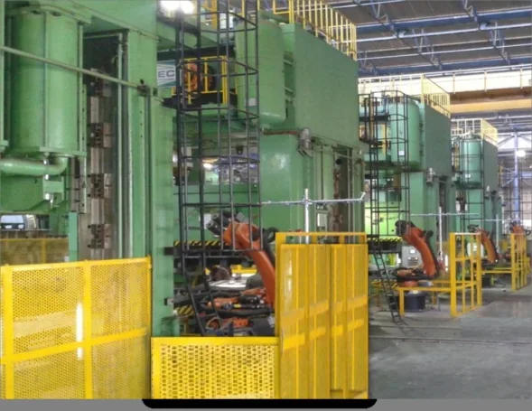
Press-line context from supplied profile. Project and site attribution are unconfirmed.
01 / Layout and handling concept
Map the transfer before specifying equipment.
A line concept considers blank presentation, destacking, centring, transfer through presses and end-of-line handling. The arrangement and responsibilities depend on the plant layout and the part family.
01Blank presentationPart and stack inputs
02Destack and centrePick and location approach
03Transfer through pressesRobot and tooling interfaces
04End-of-line handlingOutput and onward flow
Illustrative process sequence for local review. An engineering-approved line diagram and project-specific layout are still needed.
02 / Mechanical equipment
Equipment around the transfer.
Depending on the agreed design, a press-line work package may include robot pedestals, fencing, centring tables, destacking equipment and conveyors. Supplied Dynamic Tandem materials show these as equipment examples; their historical progress labels are not current delivery statuses.
Equipment interfaces, guarding boundaries and installation responsibilities need to be agreed for each line.
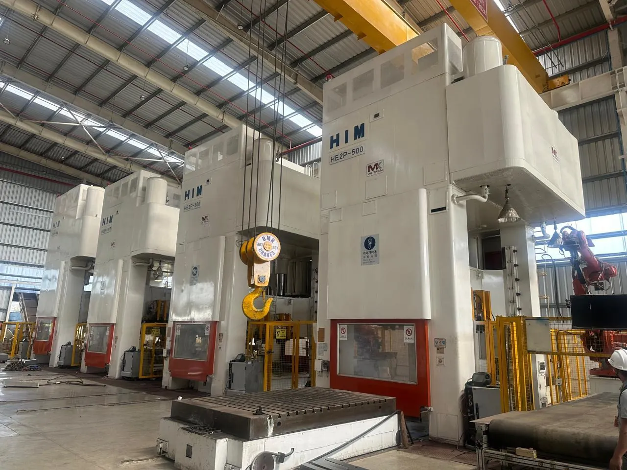
Press installation image for equipment context; no customer or delivery role is assigned to this photograph.
03 / Custom grippers
Tooling matched to the part and robot.
Gripper design starts with the part geometry, mass, handling points, robot interface and operating sequence. The CAD concept and finished component shown here are separate supplied examples; they are not presented as stages of one project.
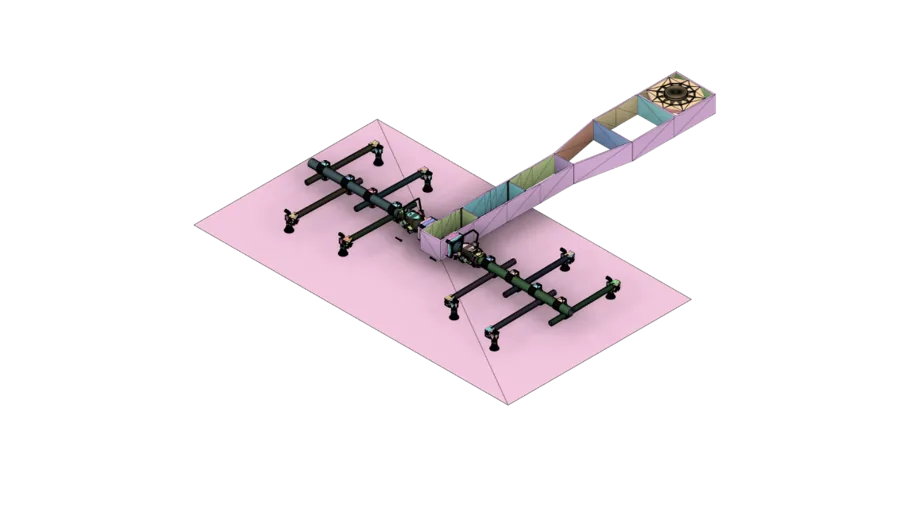
CAD concept from supplied profile; project association pending.
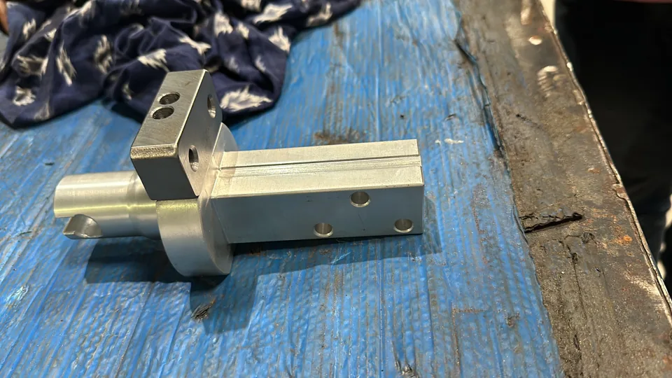
Separate machined component example; not claimed as the finished CAD concept.
04 / Controls and programming
Connect the line sequence to the control system.
Review the available press interface, PLC and HMI architecture, safety interlocks and robot programming scope. Programming, integration and commissioning should be defined against the existing controls and agreed acceptance criteria.
Define the interface
Press signals · robot I/O · tooling controls · HMI functions · interlocks · commissioning and test responsibilities
05 / Selected references
A Gujarat configuration for client review.
Supplied records describe the Gujarat work as jointly delivered with KUKA for SKH Y-Tec. The configuration below is internally consistent across the reviewed materials, but customer naming, dates, SVS scope and matching media still require approval. It is an unapproved reference candidate, not a published case study.
1250T line
6 presses · 8 robots
800T line
5 presses · 7 robots
500T line
4 presses · 6 robots
Internal-review figures only. Do not sum these with other records or associate current page photos with this reference without approval.
06 / Operating demonstration
Show the running line with its confirmed record.
Supplied operating footage can support this page once a web-ready edit is prepared and matched to the correct installation. A project ID, customer and site attribution, approval to publish and accessible video description are needed before it is embedded.
Demonstration pending
No footage is currently assigned to the Gujarat, Pune or Nashik references. A still image and caption will accompany any approved video.
Discuss your press line
Start with the line and the part.
Send the press arrangement, part details, transfer requirement and current controls so the engineering and delivery scope can be reviewed.